Advanced Aspects of Digital Audio
Collected for the inquisitive audio enthusiast
On this page we will be looking at several advanced aspects of digital audio which I feel are not really common knowledge among audio enthusiasts but deserve to be.
Digital audio basics
For obvious reasons, a comprehensive introduction into digital audio is beyond the scope of a web page like this. The basics discussed here stem from like three or four different lectures, from Signals and Systems (Fourier transform, convolution, time and frequency domain basics, sampling basics) and Communications Technology (complex exponentials, double sided spectra) to Integrated System Design (SNR, ADC and DAC stuff).
Representation of waveforms
What is commonly called a "digital signal" has two important properties: It is discrete-time with quantized amplitude.
This means that it consists of a stream of sampled values (usually obtained by averaging over a very small time slot and thus about the same as the instant value at a certain time) at fixed intervals. These values are stored with finite accuracy, usually in binary numbers 8, 16, 24 or 32 bits long (for a total of 256, 65536, 16777216 or 4294967296 discrete values, respectively).
Here's a very simple digital waveform:
    ^
    |
+3 -+  X                                               X
    |
+2 -X     X  X                                   X  X
    |
+1 -+           X                             X
    |                                                       t
 0 -+--|--|--|--|--X--|--|--|--|--|--|--|--X--|--|--|--|--> --
    |  1  2  3  4  5  6  7  8  9 10 11 12 13 14 15 16 17    T
-1 -+                                                        S
    |
-2 -+                 X                 X
    |
-3 -+                    X  X  X  X  X
    |
-4 -+
    |
TS is the sampling interval, the more
commonly used inverse fS = 1 / TS is the
sample rate. The sample values are marked with X.
Well, this was intended to be a sine (or cosine) with amplitude 3 and a periodicity of 16 samples, represented in 3-bit signed integers (thus giving a total of 2³ = 8 discrete sample values). The sample values were easily obtained with a pocket calculator, then rounded down to the next lower integer.
Implications of sampling
Sampling theorem
So you turn your average continuous-time (analog) signal into a stream of numbers sampled every so and so many microseconds. The information about what the signal does in between is obviously lost, but where does this make itself felt? The answer is given by Nyquist's sampling theorem:
A signal sent through a sampling system running at sample frequency
fS cannot be accurately reconstructed if its bandwidth
is half of fS or greater.
A sampling system here is something that takes a continuous-time signal, samples it and aims to reproduce the continuous-time signal at its output by means of suitable interpolation.
Note that I used a fairly general formulation here. That's for good reason
– you are not restricted to a chunk of the frequency spectrum containing
0 to fS/2 (although that is the normal
case for digital audio), it would work just as well for
fS/2 .. fS, fS ..
3 fS/2, or generally
m * fS/2 .. (m+1) *
fS/2
, m being an integer.
The selected chunk
must be the same on both ends of the system, of course, and in practice you are
quite likely to get into trouble with higher values of m. If we
use different spectrum chunks on input and output, we have built a sampling
mixer, which is occasionally used for RF work.
A positive formulation is also called the Nyquist criterion:
A band-limited signal can pass through a sampling system without loss if
its bandwidth fmax is less than
fS/2.
In practice for digital audio, this means that the highest
reproducible frequency is a fraction under fS/2. The
common Compact Disc with fS/2 = 44.1 kHz therefore
stops short of 22.05 kHz. Given that even very young children can barely
hear up to 20 kHz and us slightly older folks can consider ourselves lucky
if we get up to 18 kHz (currently it's about 16.5 kHz for the
author), that should do. Luxury it is not, of course, requiring very steep
filtering in order to both retain a good frequency response and keep
high-frequency content above fS/2 from giving trouble,
but one wanted to keep the amount of data to the minimum necessary.
Frequency domain considerations, reconstruction and aliasing
In order to understand what happens if the signal bandwidth gets too large, you have to know that:
Sampling in time domain is equivalent to periodicity in frequency domain, and vice versa.
While you may not find this entirely intuitive (it is shown using the properties of the Fourier transformation), you have certainly seen examples for the "vice versa" case – think of any nicely periodic function like sine, square wave or triangular wave and what those look like in frequency domain. You'll typically have a fundamental and a number of harmonics, or in other words a bunch of equidistant discrete lines in the spectrum, which means that the spectrum is sampled. Throw in the symmetry of the Fourier transformation, and the first case seems a little easier to believe at least.
Now let's look at the two-sided power spectrum of some band-limited audio signal:
               ^ power density
          __   |   __
         /  \  |  /  \
        /    . | .    \
       /     | | |     \
      /      | | |      \
...--+---------+---------+----> frequency
     |         |         |
    -f         0        f
      max                max
This same signal sampled at frequency fS, with the
Nyquist criterion fulfilled:
             ^ power density
        __   |   __                       __       __
       /  \  |  /  \                     /  \     /  \
...   /    . | .    \                   /    .   .    \   ...
     /     | | |     \                 /     |   |     \
    /      | | |      \               /      |   |      \
---+---------+---------+------+------+---------+---------+--->
   |         |         |      |      |         |         |  f
 -f          0        f      f     f - f       f       f + f
   max                 max    S     S   max     S       S   max
                             --
                              2
Now the spectrum of the original signal finds itself repeated every
fS ad infinitum, in both directions. In order to
reconstruct things, we can conveniently employ a lowpass filter that lets
through the desired parts only. Ideally, such a filter would look like
this:
                   ^ filter amplitude
                   |
  +----------------+1---------------+
  |                |                |
  |           _    |    _           |
  |             \  |  /             |
  |         /      |      \         |
  |              | | |              |
  |       /        |        \       |
--+------+---------+0--------+------+---> frequency
  |      |         |         |      |
-f      -f         0        f      f
  S       max                max    S
 --                                --
  2                                 2
In this case a slightly less ideal one would also do. Now "sending things through the filter" amounts to multiplication in frequency domain, so it is clear that the above filter will remove all the unwanted components.
If you look at things in time domain, this filter is called an interpolation filter. It "fills in" the reconstructed signal between the given sampled points in a sensible manner. Since our output signal is supposed to contain only the original components, i.e. have a non-periodic spectrum again, it must obviously be continuous and no longer sampled in the end.
Our ideal filter above, btw, would have a sinc or
sin(x)/x type impulse response, so there you have your "sinc
interpolation". One problem with this kind of filter is that its impulse
response has infinite length, which is obviously a problem if you want to
carry out your filtering (convolution) in finite time. Real-life versions
therefore have to cut off at some point, compromising on the filter
properties somewhere.
Now let's look at what happens if the Nyquist criterion is not fulfilled:
             ^ power density
 ..._   __   |   __   __       __   __       __   _...
     \ /  \  |  /  \ /  \     /  \ /  \     /  \ /
      X    . | .    X    .   .    X    .   .    X
     / \   | | |   / \   |   |   / \   |   |   / \
    /   \  | | |  /   \  |   |  /   \  |   |  /   \
---+---------+------+--+---+------+------+---------------->
   |         |      |  |   |      |      |              f
 -f          0     f  f    f     3 f    2 f
   max              S  max  S       S      S
                   --              --
                    2               2
Oops. That looks a bit messy, doesn't it? All the spectra are overlapping each other. Reconstruction here obviously isn't possible unless you know something about the structure of the original signal (where special filtering may still be able to save something), and in audio there are fairly few assumptions one can make about it. The introduction of new unwanted signal components through "mirrored" frequencies is called aliasing.
How does one deal with signals of overly large bandwidth then, given that they are not that exotic in real life and may need to be digitized anyway? Simple: Filter out the offending components beforehand, with what is unsurprisingly called an anti-alias filter.
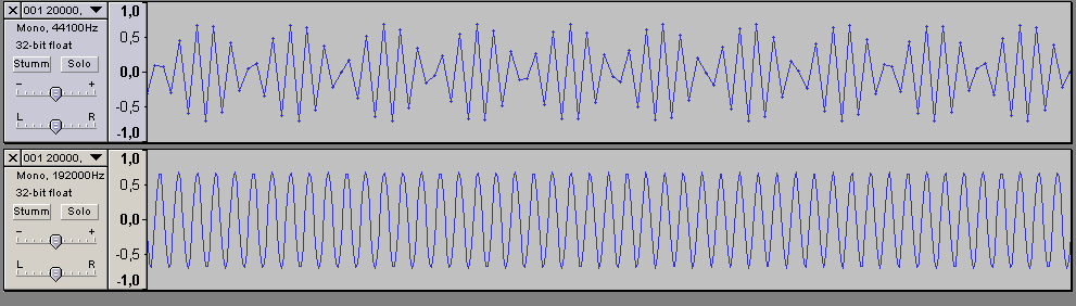
High-frequency sines look strange?
You have certainly seen that signals with frequencies close to
fS/2 look a little strange, with what should be a
sine "pulsating" somehow if you look at it in an audio editor. Now the question
is, does it actually come out like this after D/A conversion? The answer is:
No, it doesn't! It's just that the audio editor uses a lousy
interpolation function, not infrequently linear (i.e. connect sample values
with straight lines), which gives decent results for low frequencies (and is
fast) but does not work well close to fS/2.
I have taken an example file (20 kHz sine sampled at 44.1 kHz) and upsampled it using SSRC (to 192 kHz), then displayed both in Audacity. SSRC uses very high-quality interpolation, with almost ideal filtering. And as you can see, the upsampled file shows a nice sine, like it should. The "beating" in the original file comes from the 20 kHz tone's alias at 24.1 kHz, which is not well suppressed by the linear interpolation "filter" used for display. That's all.
Another effect resulting from a finite sample rate is the phenomenon of intersample overs.
The "in between the samples" myth
Some people claim that due to the samples taken at discrete points in time,
the sampled system "doesn't know" what's going on in between, thereby "missing
information". Well, this is not true. What they're forgetting about is the
band-limiting anti-alias filter during A/D conversion and resampling. Anything
unusual happening in between two samples would have to occur at higher
frequencies than fS/2, and that's filtered out.
Conversely, during D/A conversion the interpolation lowpass smoothes out the
"steps".
Implications of quantization
Let's take a look at our sample waveform again:
    ^
    |
+3 -+  X                                               X
    |
+2 -X     X  X                                   X  X
    |
+1 -+           X                             X
    |                                                       t
 0 -+--|--|--|--|--X--|--|--|--|--|--|--|--X--|--|--|--|--> --
    |  1  2  3  4  5  6  7  8  9 10 11 12 13 14 15 16 17    T
-1 -+                                                        S
    |
-2 -+                 X                 X
    |
-3 -+                    X  X  X  X  X
    |
-4 -+
    |
Like I stated, this was intended to be a sine (or cosine) with amplitude 3 and a periodicity of 16 samples, represented in 3-bit signed integers (thus giving a total of 2³ = 8 discrete sample values). The sample values were easily obtained with a pocket calculator, then rounded down to the next lower integer. Sounds like a stupid rounding method, doesn't it? Yep – just right for a computer. For the machine, this means no more than throwing away the less significant bits, which is dead easy. (Things are not much different in A/D converters.) Conventional mathematical rounding, by contrast, requires quite a bit of computation.
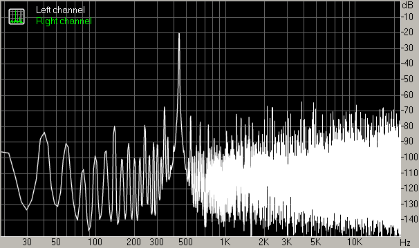
When digitizing our poor sine above, we have apparently introduced some distortion called quantization noise. This is not random noise but in fact correlated with the signal itself, and typically is anything but harmonic distortion – so it can be clearly audible. In fact, a pure 440 Hz sine at a level -20 dBFS generated with Foobar2000 as a 44.1 kHz 24 bit file and then reduced to 8 bit samples with no further measures clearly shows a gritty noise accompanying the main tone.
The problem in this case: The original signal was not sufficiently random. You need a sufficient amount of noise in order for the quantization error to become equally distributed and the quantization noise to become decorrelated from the signal. With a certain amount of noise, the signal can "jump" between two values in order to approximate one in between, so to speak. You need to be careful with intuition here, however; you'll see why in the next section.
If the original signal was sufficiently random, the maximum signal to noise
ratio to be obtained with n bit samples is given as
SNR   = (6.02 n + 1.76) dB
   dB
Or as a rule of thumb: 6 dB per bit.
This works out to SNRs of about 50 dB for 8 bit samples, 98 dB for 16 bit samples and 146 dB for 24 bit samples, respectively.
Now assume you have a very clean signal, quantized maybe with 24 bit samples, and for some reason want to store this with 8 bit samples without having it sound like crap. In such a case you can deliberately add noise with specific properties. This technique is called dithering. More on this later.
A practical note
When doing audio editing, it is beneficial to use a larger intermediate sample size, as otherwise new quantization errors will be introduced in each step and quality may ultimately suffer audibly. 8 bits more than the final desired sample size are usually fine (one exception are floats, which are only found as 32-bit with a 24-bit mantissa and 8-bit exponent). The final output would be yielded by dithering down.
Sampling and quantization combined
Interactions
Since digital audio systems tend to use both finite sample rates and sample lengths, one might ask whether there are any groundbreaking new effects when they are combined. As far as I'm aware, there aren't any, but there are some interactions.
Note how the SNR formula makes no reference to sample rates at all. This can only mean that for any fixed sample size, the noise power must remain constant regardless of sample rate. Or in other words, if you use a higher sample rate, the noise can spread over a larger bandwidth and therefore the spectral noise density will be lower – 3 dB per doubling of sample rate, to be precise. If the receiving end is only interested in part of the bandwidth, effective SNR can therefore be increased. This is referred to as oversampling.
Dithering
It becomes interesting when dithering comes into play. As we know,
this refers to the addition of noise with certain properties upon reduction of
sample length in order to lend the signal a sufficient randomness. While it is
fairly clear how the noise should best look like statistically, there is some
degree of freedom as far as the spectrum is concerned. By means of noise
shaping, noise power density can be redistributed, away from frequencies
where the noise might be easily heard and towards other ranges that are less
critical, increasing effective (perceived) SNR. Hearing threshold based noise
shaping is pretty much a standard feature in audio applications and sample rate
converters these days, along with the simpler triangular (rising towards highs)
shape and standard white noise (flat spectrum).
There is one twist, of course: For noise shaping to work, you need to have
spare bandwidth to begin with. When faced with a sample rate of 8 kHz (as
used in telephony), you may very well find no noise shaping (flat spectrum) the
least obtrusive variant – unsurprisingly so, given that ATH based noise
shaping can't be used (sample rate too low) and the triangular version has most
of its energy in a region where the human ear is the most sensitive.
Dithering experiments
If you want to experiment with dithering, I'd suggest Foobar2000 or Audacity for tone generation, SSRC for dithering (and sample rate conversion) and Rightmark Audio Analyzer for spectra (the latter doesn't do less than 44.1 kHz though). Keep the level of test tones low, -20 dBFS seems like a decent starting point for 8 bit samples.
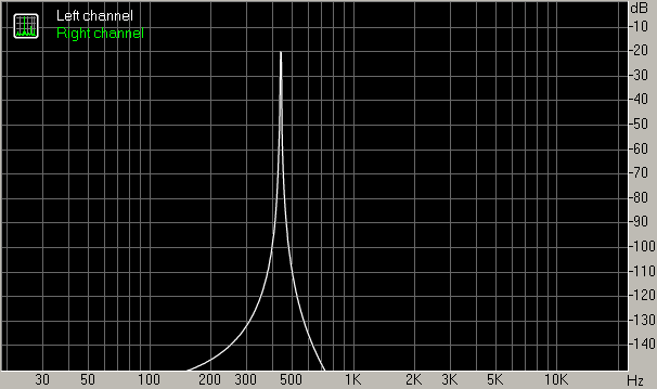
Here are a few examples of spectra obtained with just this combination of tools (RMAA settings: 16384 point FFT, no zero padding, overlap 75%, Hann window):
- 440 Hz original waveform (24 bit 44.1 kHz)
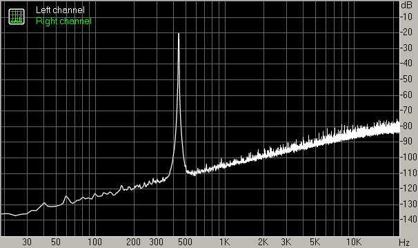
- 440 Hz waveform converted to 8 bit samples, no dither
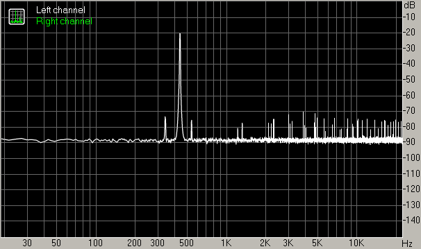
- 440 Hz waveform converted to 8 bit samples, white noise dither with Gaussian p.d.f. of default amplitude
- 440 Hz waveform converted to 8 bit samples, white noise dither with Gaussian p.d.f. of amplitude 0.36
- 440 Hz waveform converted to 8 bit samples, triangular spectral shape dither with Gaussian p.d.f. of amplitude 0.36
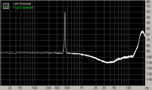
- 440 Hz waveform converted to 8 bit samples, ATH (hearing threshold) based shaped dither with Gaussian p.d.f. of default amplitude
Apparently the default amplitude for the Gaussian p.d.f. in SSRC 1.30 is fine for ATH based dither but not sufficient for white noise or triangular shaped dither.
The example above has the advantage that you can actually listen to it and judge things by ear. In this case, the most elaborate dithering method – using noise shaped according to the hearing threshold – gives the best subjective result, with not only the distortion disappearing, but noise almost vanishing as well.
Interestingly, the results when using a combination of 19 and 20 kHz
sines (to check how things behave as we get closer to
fS/2) are not much different, although they do show the
ranking of noise probability distribution functions more clearly, which in
terms of suppressing spurs come out as Gaussian first, then triangular, and
rectangular last (unsurprisingly).
Intuition would suggest that dithering works less well as the signal
reaches higher frequencies and moves towards fS/2, but
this is quite clearly not the case – intuitive understanding
unfortunately fails here.
Similar tests (at even more extreme bit depth or rather shallowness, a whopping four bits) with samples to listen to can be found in this article by Werner Ogiers.
Practical A/D and D/A conversion
Nowadays A/D and D/A converters (usually called ADCs and DACs, respectively) come as ICs containing all the important components.
For an ADC, this would be:
- anti-alias filtering
- the A/D converter itself
And for a DAC:
- D/A converter
- interpolation filter
The converters themselves are usually higher-order Σ-Δ (sigma-delta) types with 1-bit or few-bit converters running in the MHz range and plenty of noise shaping. The filters are usually digitally implemented (after A/D / before D/A), with only a minimum of external filtering being necessary due to the high internal sample rates.
What can be confusing when working with DACs is that things are called "DAC" on entirely different levels. You can buy a device called "DAC" for your stereo that takes mains and a digital signal and converts it to analog, but the IC that actually does it will also be called a DAC, and this again usually contains a digital filter and the D/A converter itself, which may also be referred to as a DAC.
Sample rate conversion
Sample rate conversion is a common practical problem. Typical applications include:
- Playback of material with a sample rate not natively supported in hardware
- Mixing of several audio streams of different sample rates
- CD mastering (digital audio workstations commonly employ sample rates of 96 or 192 kHz, usually also with 24-bit or 32-bit samples, so dithering as discussed in the last section is also required)
In theory, sample rate conversion is basically D/A and A/D conversion in series – actually I wouldn't be surprised if this had been the method of choice in the olden days, when available processing power was far more limited than today. So what you need to do basically is:
- Determine lowest common multiple of the two sample rates involved and create new stream of samples at this rate.
- Insert existing samples and leave the ones in between at zero.
- Apply lowpass (interpolation) filtering as in a DAC, i.e. with the passband extending to half the original sample rate. This "fills up" the previously zeroed samples, as you'd expect an interpolation filter to do.
- Apply anti-alias filtering with a passband up to half the new sample rate, as in an ADC.
- Now pick samples at the desired new sample rate.
In practice, you would contract the two filtering stages to one (which can still contain a multi-stage filter and in fact frequently does in order to combine the advantages of different filtering approaches).
Like any kind of digital processing that involves interpolation, resampling may be affected by clipping through intersample overs, as shown for an Aqvox DAC (presumably with upsampling to 192 kHz enabled).
A typical practical problem you'll find is that things take too long. In a real-time system, you can only afford so much delay - you wouldn't want your gaming sound to lag noticeably behind the screen output, for example. So frequently some "cheating" is required, for example:
- Compromise on filter characteristics (possible aliasing) by allowing for lower impulse response length; in any case try to find a filter topology that gets things done in the lowest time
- Decrease computational accuracy
- Use a less high intermediate sample rate and pick the sample that's closest to the position desired, with an eye on the introduced jitter
Conversely, when timing is not critical, you can strive for optimum quality. Here's a (Flash-based) page that allows comparing various software resamplers. SSRC (high precision executable) does pretty well save for some ringing around fs/2, though as a Linux user I'd go for SoX with the linear-phase VHQ setting instead. It's quite interesting how badly a number of expensive commercial applications fare in this discipline.
Another practical issue is ringing, caused by time-domain smearing of signal components near/in the transition band of very steep lowpass filters. (As seen for two different filters on spectra here.) While not a problem for sample rates of 44.1 kHz or higher, care should be taken when dealing with ones where the transition band is comfortably inside the audible range.
Processing chain pitfalls
Intersample overs (and their connection to NOS DACs)
Clipping and levels
So far we have not touched another aspect of quantization: Maximum values. For the typical 16 bit signed samples as you'd find on a CD, the possible range of values is -32768 to +32767 (for a total of 65536). What, then, does a typical ADC do if you try and offer it some input voltage which would lead to a value outside this range? It'll record the nearest permitted value, so e.g. +39676 will be recorded as +32767 and the rest "cut off", therefore this is called clipping.
If you want to record an undistorted sine, it obviously has to fit within the permitted range. The level at which the signal just touches the limits is called "full scale" and defined as 0 dBFS. (Another definition also finds use, however, referring to this full scale sine's RMS level and calling it -3 dBFS. Here a full scale square wave has 0 dBFS, and everything ends up 3 dB lower than with the other definition.)
Trivia: Reportedly there were early CD players that treated full-scale samples as errors. I don't know how much truth there is to that, however.
DACs and filtering
In the olden days, D/A conversion still was very straightforward: You would
run a multi-bit DAC at sample rate, which would dutifully output its sample
values, then a bunch of analog filter circuitry would take care of all the
high-frequency components (repeated spectra). (If you didn't filter these out,
following electronics or speaker drivers might object audibly or even
destructively.) However, the sample rate of e.g. a CD means that you have to
have very steep filtering in order to suppress these well, since a 20 kHz
sine (still in passband) has its mirrored counterpart at 24.1 kHz. This is
either very expensive, leads to uneven group delay across the passband (not
like we could actually hear it...), worsens audio quality (opamp filter stages,
depending on implementation and type) or all of that.
First-generation Japanese CD players actually looked like that. In fact,
they typically also used a single DAC that got switched between the two
channels rapidly, leading to a delay of half a sample clock between left and
right. You normally wouldn't notice, at least during speaker playback, as this
is the equivalent of being like 4 mm further away from one speaker, though
a mono downmix would give a 3 dB dropoff at
fS/2.
The guys who constructed the first Philips CD players were a little smarter
than that. They thought on how they could save on analog filtering and shift
most of it to the digital domain instead. The answer was called "oversampling".
The DAC was run at a multiple of the original sample rate (first 4 times,
increased to 8 times later on), and preceded by a digital sample rate
converter (for upsampling) and filter (usual interpolation filter). Now given
that the digital filtering yielded a decent suppression of unwanted components,
the first "mirror" of a 20 kHz signal moved from 24.1 to a
whopping 152.2 kHz, reducing the filter requirements considerably.
Nowadays the DACs themselves have different topologies, but the filtering
concept has not changed.
"Mean" signals
It is possible to generate digital signals which after interpolation
(lowpass filtering) have an amplitude larger than full scale! One example is
a sine of frequency fS/4 with a phase shift of 45°.
You never record its peaks, but instead always sample at points where the
level is only sqrt(2)/2 of the sine's amplitude. This you can do
at full scale, of course, resulting in values of +32767, +32767, -32768,
-32768, +32767, +32767, -32768, -32768...
Now any kind of interpolation, which is the same as lowpass filtering,
will lead to peaks larger than full scale – 3 dB larger in this
case. As it occurs "in between" samples, this phenomenon is called "intersample
over". This is uncritical as long as filtering is done in the analog domain
(assuming the filter circuitry has enough headroom in terms of supply voltages,
which is usually the case), but what happens in a digital filter?
Don't think this is academic – SSRC doesn't have the "twopass" option
for no reason. And indeed, a track on a current pop CD (released late 2007,
Replaygain album gain -9.55 dB, so mastered to about -7.5 dBFS,
which is not untypical) peaked at +1.975 dB when resampled to
192 kHz. (It gets even worse when the same material is encoded in a data
reduction format such as MP3, where band filtering results in overshoot due to
Gibbs' phenomenon. On another current pop album mastered to about
-9 dBFS with lots of clipping, I saw a peak level of +3.6 dB for the
resulting files. Your DAP better had some decoding headroom...)
For more examples and a more in-depth treatment, see this paper by TC Electronic A/S. A few more consumer electronics devices tested.
Overflows in digital filters
When the first digital filters were constructed, the levels on CDs were pretty modestly chosen, and clipping rarely occurred, if ever. Therefore, hardly anyone thought much about what might happen if a value greater than digital full scale were computed.
Digital filters commonly operate with sample values represented in the
two's-complement system. Here the largest possible positive value is coded
as 01111...1. During an undetected overflow, 1 might be added
to this, which brings us to 10000...0 – which
unfortunately happens to be the lowest possible negative value!
In case of 16 bit samples, this brings us straight from +32767 to
-32768. Oops. That might not sound very good.
Now assume we have a simple overflow detection that proceeds to clip
overly large results. The effect here won't be as catastrophic, but still
our fS/4 sine with full-scale recorded values would
find itself pretty clipped at the peaks.
What would be a smart way of dealing with this then? Well, use a few more bits for the samples (not a bad idea anyway when doing computation) and scale down the incoming samples by, say, 3 or 6 dB (the latter would be a simple shift). You obviously lose just this amount of output SNR, but today's DACs are usually good enough that one can afford that, certainly so when CD audio is concerned.
Integrated digital filters today seem to employ the last approach, but it has apparently not propagated to a number of sample rate converters and similar things that have to carry out interpolation yet.
When using a computer as source, it thankfully is easy to implement a digital volume control.
The connection to NOS DACs
NOS DACs, not new old stock but non-oversampling DACs in this case, are DACs without an oversampling digital filter, just like in the early days of digital audio, as outlined earlier. They are typically built around older DAC chips like the venerable Philips TDA1541 and have to employ all analog filtering in order to get rid of the unwanted high-frequency components. Their insensitivity to intersample overs is, however, about the only technical merit I can see.
Funnily enough, removing the 4x oversampling digital filter from an early Philips CD player like the CD-101, thereby converting it to NOS, seems to lead to some really ugly artifacts on an intersample-over test signal, while unmodified the unit is relatively well-behaved. That shows once again that while they may not always be 100% right, the engineers constructing these devices usually know pretty well what they're doing – which is a lot more than one can say about a great many "audiophile tuners".
Filter pre- and post-echos
It has been known for about ten
years now that digital filters with periodic passband ripple cause pre-
and post-echos, similar to the way
data
reduction systems (think MP3) may. With
about 60 dB of dynamic range being typical for home listening setups, I
would expect things to (possibly!) become audible at a ripple amplitude of
about -60 dB (deviation about ± 0.01 dB) – thankfully
basically any half-decent DAC, ADC or codec has less ripple than that, only
converters for portable use (low power) or onboard sound (low cost) may be
critical, provided they don't have far more significant weaknesses elsewhere.
If you're really picky, DAC ICs of the better kind typically allow
the selection of a "slow rolloff" digital filter characteristic, which has no
periodic ripple at all (at the expense of a minimal dropoff in the upper highs
which – at least in the DACs I was looking at – is not very likely
to be audible, and less steep lowpass filtering).
Jitter
When digital data streams are transported, the arrival times of the ones and zeros tend to vary a bit, "smearing" the transitions when looked at on an oscilloscope. This is called jitter. When looking at a reference clock oscillator (as they are needed for D/A and A/D conversion at the very least), jitter is exactly the same as phase noise, just quantified differently. Jitter may therefore be introduced by a reference clock with high phase noise, but also by non-ideal transmission environments that degrade signal quality by imposing bandwidth limitations (including phase shifts), dispersion (frequency-dependent propagation speed) and added noise (e.g. with weak received signals).
As long as we're staying in the digital domain with synchronous clocking, jitter is fairly uncritical. High jitter levels eventually degrade error rates, but as long as you manage to obtain all the data correctly and store it somewhere there will be no losses.
Jitter becomes critical during A/D and D/A conversion, plus asynchronous
reclocking. Here it amounts to phase modulation of the signal,
something closely related to frequency modulation (modulation of the
phase with some function m(t) is the same as frequency modulation
with 2πd(m(t))/dt).
Look
here for the effect of FM. High jitter levels are usually heard as sort of
a muddying and mellowing of the sound, though the type (spectrum) of jitter
signal plays an important role as well. Dunn, in his
1992 jitter paper (recommended
reading), also speculated about the influence of DAC type; given that early
1-bit (Σ-Δ) DACs are not exactly known for good jitter handling,
he seems to have been spot on.
One instructive home audio application where jitter plays a role is the
connection of an external DAC to a digital source (e.g. CD player) via the
common S/P-DIF interface (electrical or optical). S/P-DIF is a "one-way"
synchronous interface with no dedicated clocking connection, i.e. it just sends
out the data in realtime without caring about what the recipient (if any) might
be doing with it. The DAC in this case has to synchronize with the
incoming data stream, and the reference clock for the D/A converter itself
has to be regenerated from the data stream. This is usually performed
by a dedicated S/P-DIF receiver chip that also sets up the DAC for various
sample rate ranges (usually up to 48 kHz, up to 96 kHz and up to
192 kHz). The most common clock recovery method involves a phase-locked
loop (PLL).
Now a PLL usually has a certain bandwidth where it lets through the
incoming signal essentially unaltered. If the spectrum around the incoming
clock signal is quite noisy due to jitter and other effects, the recovered
clock will be far less good in terms of phase noise than that of a local
crystal oscillator. Now you could try to make PLL bandwidth very small, but at
some point it may no longer lock reliably to somewhat out-of-spec signals or
fail to follow a slightly drifting reference clock. In addition, the PLL itself
(phase detector and VCO) introduces some phase noise (and potentially spurs) of
its own. Good conventional receiver chips make use of VCXOs which have a small
pulling range but very low phase noise (e.g. AK4114), but as this requires two
external quartz crystals to cover all the common audio sample rates,
cost-sensitive applications typically employ highly integrated chips with much
noisier CMOS RC oscillators for VCOs.
What would be the best way of avoiding all this mess? Quite obviously, tell
the DAC what frequency it's supposed to use, then have it use its internal
high-quality crystal oscillator and output a reference clock which the
digital source can sync to. (A bit of buffer memory memory may be
useful but isn't absolutely required.) In fact, this approach is used in
professional studio applications, as far as I'm informed.
And the second best way? High-tech clock recovery and reclocking. A digital
PLL with variable loop bandwidth (higher for acquisition, lower for tracking)
and a DDS VCO (possibly followed up by a low-noise analog PLL to remove spurs)
seem like suitable ingredients. When using a buffer, the buffer level might be
useful for fine-tuning of the recovered clock.
Some DACs employ an asynchronous sample rate converter (ASRC) to interface
between input (potentially jittery) and local (stable) clocks. Now an ASRC is
not terribly different from a DAC clocked by input (recovered) clock followed
by an ADC clocked by output (local) clock, as outlined under
Sample rate conversion. Therefore it not only may be
affected by intersample overs (like any other digital
processing device performing interpolation), but also can't do a whole lot
against jitter (AFAICS).
After all this, it should be mentioned that jitter on the DAC side is mostly a non-issue nowadays, mainly because a lot of work has been invested to make the converters more robust over the years.
Vinyl vs. CD
To anyone who lived through the early '90s when vinyl records became seriously oldfashioned as a form of music storage and CDs with their better sound quality and far more convenient handling took over the role of medium of choice, the current situation must be truly bizarre. Many music enthusiasts nowadays prefer the oldschool big black discs again – not only because of the obvious things like bigger cover art and the higher dedication required (musical slow-food, so to speak), but not infrequently also citing better sound quality. Now anyone with some knowledge about the technical aspects of vinyl will admit right away that in fact it is a medium with a lot of limitations where distortion figures in the order of 1% are not untypical, let alone the termination mess when using MM cartridges. So where does that quality argument come from?
In my opinion, the two main reasons are:
- One limitation of the medium vinyl actually works to its advantage: You cannot make things louder without dramatically losing playtime. While CDs like other digital media have a limited maximum volume, you can still increase the average volume to some degree - that's what the infamous "loudness war" is all about, with lots of dynamic compression and clipping going on. Vinyl still has a maximum volume of sorts (if the stylus jumps out of the groove, it's too loud), but invites dynamic content with low average levels. (Of course it's equally possible to take a brickwalled mess and just reduce the volume, neatly combining the disadvantages of both vinyl and digital audio...)
- Nowadays, vinyl is sort of an audiophile niche medium (a bit like the CD in its early days), so buyers are expecting better sound quality. Record companies would be ill-advised to turn out material that's compressed to death.
It is ironic that nowadays we could make gorgeous-sounding CDs but
frequently don't and in return press better quality onto records whose
manufacturing tended to give best results some time in the '80s. Go figure.
[now playing: Kate Bush – Kite]
(Incidentally, sound quality wise I've had a lot better luck with ca. 1984-85 CDs – and, to a lesser degree, late '80s and early/mid '90s titles – than with present-day ones, which are not always, but frequently compressed to death. Remastered versions I usually avoid like the plague unless there is good reason not to, as most of them unfortunately suck. That said, I don't generally buy explicitly "audiophile" titles, which tend to be expensive and not too interesting.)