← Previous: ICF-7600D/DS / ICF-2002/2003, ICF-7600A, ICF-7600, Feature comparison, Utilities
Page Contents
- Modifications – read the disclaimer
- ICF-7600D/DS (ICF-2002/2003) mods
- ICF-7601 mods
- ICF-SW7600 mods
- ICF-SW7600G mods
- Modification of the "crippled" Saudi Arabian model
- Notes on the Italian model
- Synch mod
- Tone mod
- Extended tone mod
- Mute mod – this helps against the interruptions when tuning in single 1 and 5 kHz steps
- Light mod – for people who like to listen at night
- Another sync mod, and an AGC mod
- Telescopic antenna matching mod
- DRM mod
- ICF-SW7600GR mods
Modifications
WARNING: All the modifications here are given with NO WARRANTY IMPLIED. Be sure you know what you're doing and ask the originators of the mods when in doubt.
A number of mods are rather tricky to do. Magnifying glasses and good soldering skills are highly recommended.
ICF-7600D/DS
Full coverage mod (German and other limited coverage versions)
Interestingly there were quite a lot of versions of that radio on the market:
- AM 153-26100 kHz, FM 87.6-108 MHz, without external antenna jack, also called G-AEP model (German model)
- AM 153-29995 kHz, FM 87.6-108 MHz, with EXT ANT jack
- AM 153-29995 kHz, FM 76-108 MHz, with EXT ANT jack
- a version with lower output (0.2 instead of 0.45 Watts)
- ME model (Middle East) without SSB, reception ranges like G-AEP
In addition, the radio was shipped with or without a power supply, depending on the country.
To obtain full coverage on any version without full coverage, do the
following (according to [2]):
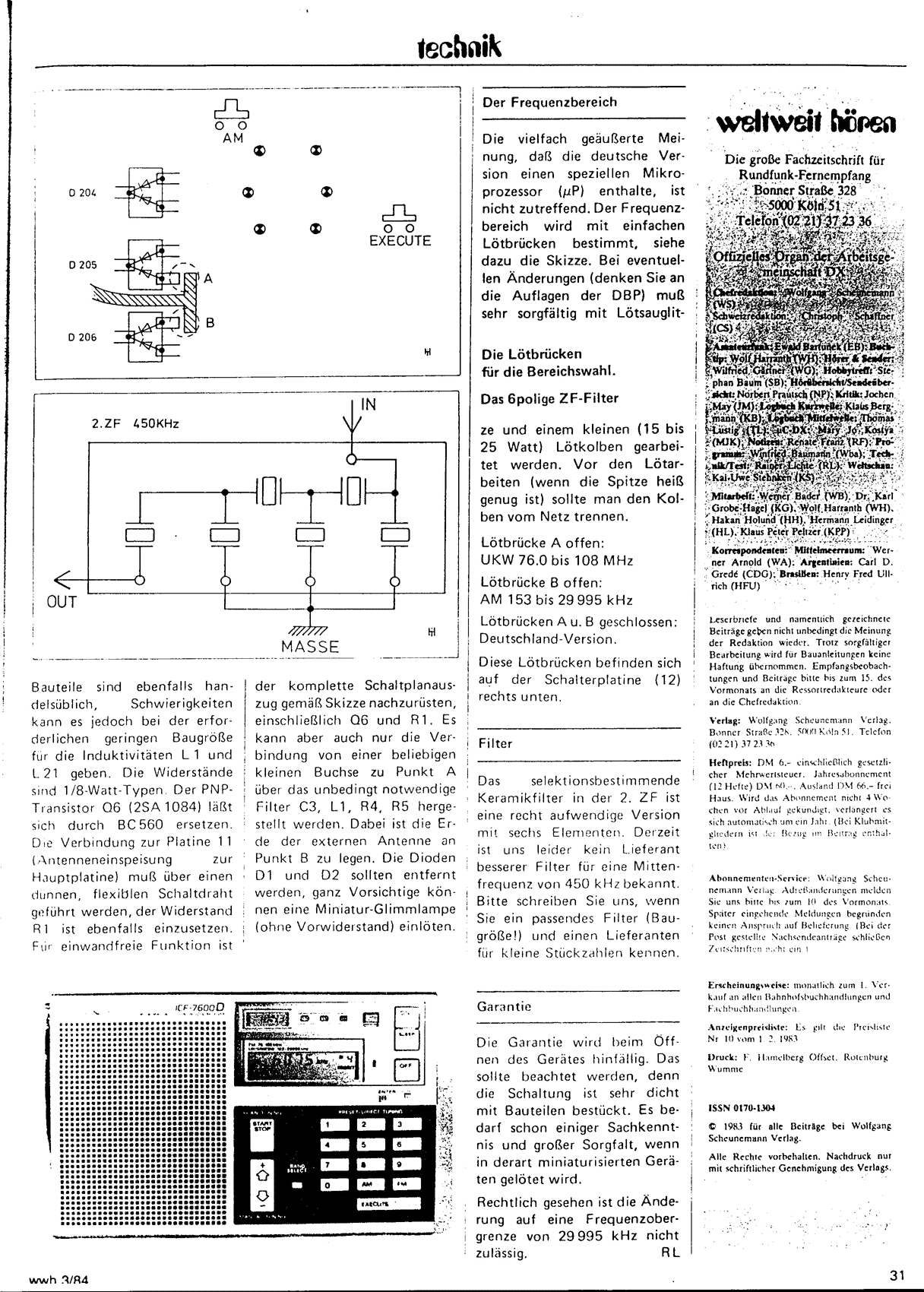
Use a small low power soldering iron (15-25 Watts). Switch it off when
it is hot enough. Locate the two small jumpers (of soldering tin) on the
circuit board (see fig. 1, positions A and B)
![[The solder jumpers]](d_ds_mod.gif)
Fig. 1 – The small solder jumpers.
If A is removed, full FM coverage is restored. If B is removed, full SW coverage is restored.
It is also possible to install the EXT ANT jack, but the procedure is a bit too long for being listed here. A look at the schematic should give you an idea about which parts have to be added.
Original article this information is based on: Modifikationen am ICF-7600D, Rainer Lichte, wwh 3/84 (AGDX e.V.), Seite 1, Seite 2
FM filter mods
The 7600D/DS has what seems to be pretty much the best FM frontend of all "7600s", but its two IF filters are just as wide as in the others (280 kHz), giving unexciting selectivity. So what are your options?
- As a starting point, I would suggest trying 180 kHz types (SFE10.7MS3 in old Murata nomenclature). They are widely available (as far as ceramic filters go), have reasonably low insertion loss, seem to stray fairly little in terms of center frequency and already give much improved selectivity. (Actually, even nominal 230s do, leading me to think that they are not too different from 180s these days.) If matched reasonably well, low distortion and good stereo separation can be achieved.
- The narrowest you can still obtain easily are 150 kHz filters (SFE10.7MJ), though it seems that one may already encounter batches that have been "cherry picked" in terms of center frequency there, meaning you may find very little close to 10.70 MHz. And with a set having 100 kHz steps, they'd rather be...
- As we move further into DXing territory, the next narrower filters are
110 kHz ones (SFE10.7MHY). Their insertion loss already is quite considerable,
which is why 110/150 kHz combos are commonly offered in mods.
Even narrower types are available with typically 80 (SFE10.7MTE) and 53 kHz (SFE 10.7MVE). A 2x 80 kHz config is not uncommonly found with FM DXers. Individual matching seems highly advisable with filters as narrow as these.
After a filter mod, one should adjust the IFT T3 in order to give best sensitivity and low distortion. Frontend alignment may also be worth a look (T1 and CT1 for 1st tracking, L20 and CT2 for 2nd tracking); optimizing it solely for 87.5 to 108 MHz will certainly result in better tracking and thus sensitivity in the FM broadcast band.
Unlike later models, this one still has a discrete ratio detector which can – and should! – be aligned to match the filters in order to give best sensitivity and low distortion. Reportedly this makes quite a difference. The respective IF transformers involved are T4 and T5.
I wonder why they put both IF filters in front of the µPC1018C (xref: AN7218) when this IC offers pins to connect a filter between its two amplification stages. Intermod characteristics? The effect on noise figure should be small, but limiting might be worse this way.
Dual-gate second mixer
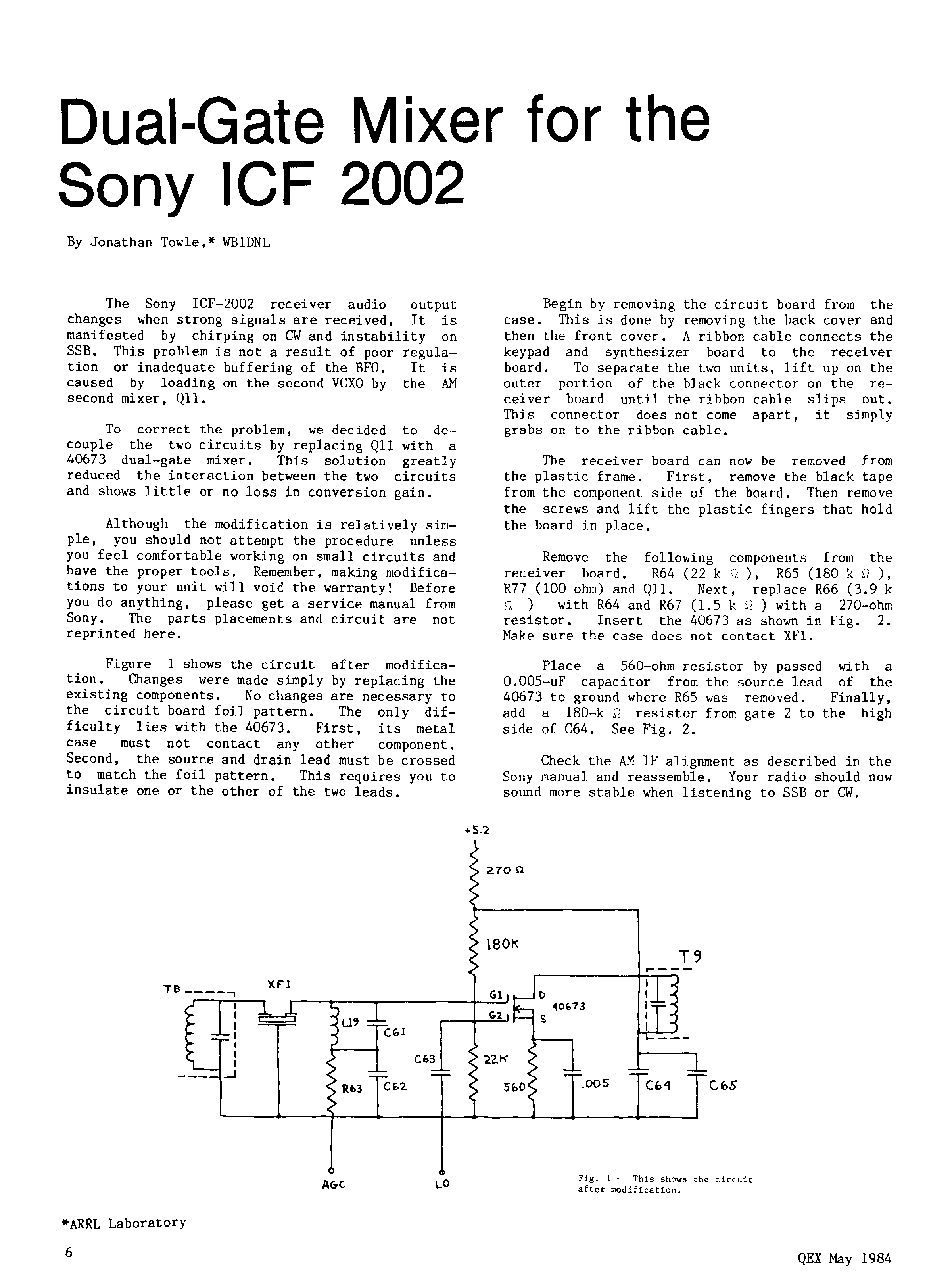
The 7600D/2002 was found to suffer from oscillator pulling on strong SSB stations, caused by pulling of the 2nd LO by the AGC. (This is different from current models, which suffer from some 1st LO pulling.) The article 'Dual-Gate Mixer for the Sony ICF-2002' by Jonathan Towle WB1DNL, published in the May 1984 edition of ARRL's QEX magazine on pp. 6-7, describes a fix which basically consists of replacing the 2nd mixer JFET by a dual-gate FET with the input signal and LO signal being fed to one gate each. Not exactly a beginner's mod and probably not very attractive today (a 7600G/GR is a whole lot better suited for SSB to begin with), but a nice solution.
Page 6: Main article, schematic
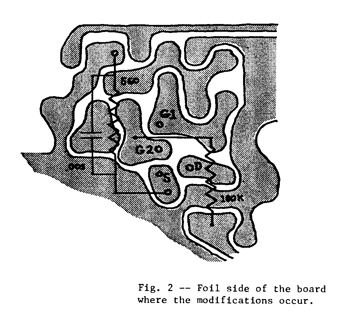
Page 7: Parts installation drawing
Reprinted courtesy May 1984 QEX.
Note that Sony fixed this problem in later (approx. 1985 onwards) samples, so these will not require this mod.
Notes on SSB-deprived Saudi Arabia / Middle East models
If you should be the unlucky owner of an SSB-deprived ICF-7600D(S) or
ICF-SW7600 and considering to modify it to receive SSB, better forget about it.
You'd have to equip the BFO and product detector with parts, which include
an IF transformer, a crystal, a few transistors, diodes, and some Rs and Cs.
Even provided you could find all the parts required, it would still be a rather
lengthy procedure.
If you're looking at used units, don't buy one of these "cripples" hoping
to restore SSB capability!
DRM mod
External link: DRM modification – I'd never have known about the filter change in the course of time without this document, so a big THANKS goes to the author. It seems phase noise still is a problem at times, but at least DRM is doable with "ye olde 7600D", no mean achievement for an early 80s PLL rig like this.
ICF-7601
The biggest weakness of this rig is the intermodulation behavior of the second mixer – and this in spite of the FET already being quite heavily source degenerated at 33 kOhms. The problem basically is that the rx is constructed like a gain-limited low-voltage design and has too much gain (especially) in the RF amp and (not so much) the 1st mixer in combination with a wideband 1st IF, plus I guess the 2SK209-Y in the second mixer just isn't that great in terms of linearity.
What one might try:
- Redistribute gain from the frontend – apply some source degeneration (or some other way of getting negative feedback) to the RF amp which is currently running at full throttle because of C7, then add a gain stage behind the second mixer, maybe between T2 and the ceramic filter. This is not for the faint of heart, of course.
- Experiment with the value of pull-down resistor R15 (47k) to ensure that switching diodes D6, D7 are doing their job properly.
- Increase LO output. This is not trivial, as one should be careful when messing with carefully tuned oscillator circuits. One could try decreasing the value of R30 (presently 3k9) to allow a higher V_CE and thus output voltage swing.
ICF-SW7600
Restoring frequency coverage
The solder jumpers mentioned in the 7600D mod section above also exist with the ICF-SW7600 model. Fortunately they are already marked so you know which jumper belongs to which frequency range. If in doubt, obtain the service manual. Please note that extending the FM frequency range to 76 MHz makes the thing tune in 100 kHz steps vs. 50 kHz steps when coverage starts at 87.5 MHz.
Notes on SSB-deprived Saudi Arabia / Middle East models
If you should be the unlucky owner of an SSB-deprived ICF-7600D(S) or
ICF-SW7600 and considering to modify it to receive SSB, better forget about it.
You'd have to equip the BFO and product detector with parts, which include
an IF transformer, a crystal, a few transistors, diodes, and some Rs and Cs.
Even provided you could find all the parts required, it would still be a rather
lengthy procedure.
If you're looking at used units, don't buy one of these "cripples" hoping
to restore SSB capability! (It might, however, be a nice candidate for a DRM
mod when obtained cheaply, since the EXT ANT jack – which tends to be useful in
escaping from PC generated interference – is usually present.)
DRM mod
A DRM mod similar to the simple one suggested for ICF-SW7600GR and ICF-SW7600G should be possible.
ICF-SW7600G
Modification of the Saudi Arabian model
Modifying the Saudi Arabian model (for SSB reception) has been discussed in the newsgroup rec.radio.shortwave. On Jan 28, 1999, Adam Trent Phillips who – at that time – had the e-mail address <jl110@cleveland.Freenet.Edu> posted the following message there:
Subject: 7600G Saudi version- a mod is in sight !
Date: 29 Jan 1999 02:40:21 GMT
From: jl110@cleveland.Freenet.Edu (Trent Phillips)
Organization: Case Western Reserve University, Cleveland, OH (USA)
Newsgroups: rec.radio.shortwave
I have been chatting with an SWL in Germany, Helmut, who as the Saudi version of the 7600G. For those not familiar, the Saudi version has the following frequencies locked out.
        FMBC: 76.0   - 87.4   MHz
          LW: 286    - 529    KHz
          HF: 26.101 - 29.999 MHz

          Single Sideband (SSB) is also disabled.
I obtained the service manual for the 7600G, which includes the complete schematic and PC board layout. According to the manual and talks with Helmut the differences between the Saudi and Japanese (which is sold in the English speaking world along with all of North and South America as far as I can tell) versions are not that great.
- On the Keyboard circuit board, forward side, there is a small solder jumper marked as "Saudi Arabia Model" in the manual and "EA SHORT" on the Saudi version board. It is located just "south" of D202 and "west" of a cluster of SMT chip capacitors (C211,C212,C213 & C214). Look in the "southwest" corner of the board.
- RV402, a 50K pot for the SSB FINE TUNE is missing. The place it would take up on the right hand side of the receiver is covered up.
- There is a extra "notch" (as I imagine it, as I have not seen it) on the case that prevents the AM MODE switch from being switched into the SSB position.
Helmut told me that after the jumper was removed _full_ frequency coverage was restored ! I have given Helmut the Sony part numbers for the SSB FINE TUNE pot and knob.
The jumper in question connects one the anodes on D202 (a dual diode package with a common cathode connected to pin 48/KO on the LCD driver IC) to the pole of the CHANNEL SPACE switch (S302). The pole of this switch is connected to B+ via a diode and a 22K resistor. The other Anode of D202 connects to a row on the keypad.
I ask that anyone who is attempting this mod to restore full function to Email me, I would like to get some experiences from people and write up a detailed procedure. I even hope to find someone in the Cleveland, Ohio area to scan a few pictures of my radio's guts.
Note: I also have the pin-out for the uPD1724GB-SR7167J and uPD1724GB-SR7167IT chips that Sony uses as the LCD driver/controller IC on the 7600G. The "IT" chip is only used on the Italian versions, all other use the "J" version. Anyone who wants pinouts on ANY of the ICs used on the 7600G can feel free to Email me.
--
Questions about Shortwave radio or AM radio ? Email me !jl110@cleveland.freenet.edu
Some time after including this posting, I got e-mail from Helmut Brandt (the SWL from Germany) and he told me that after installing the necessary parts, cutting a hole for the tuning wheel and removing the jumpers in question, his Saudi Arabian model now is an international one, so it seems the mod works :). What follows is an excerpt from a post from him in rec.radio.shortwave, dated March 18, 1999, subject "ICF-SW7600G Saudi-Arabia" (found thanks to the whole newsgroup archive from 1995 onwards being available at groups.google.com again):
So here in short, what needs to be done to convert a 7600G Saudi model to "normal".
- remove solder bridge (labelled Saudi Arabia Model) lower right of D202, sitting lower left of IC201, which is located below the Display Panel. This brings radio to normal range i.e. 150KHz to 30 MHz.
- If You want SSB after mod,
- order parts from Sony, part numbers come here:
- RV402 1-223-450-11 Res.Var. Carbon 50K (SSB Fine Tune)
- 3-914-401-01 Knob (Vol.) (Vol. and SSB Fine Tune having same shape) [Ed. note: but the pots are logarithmic for volume vs. linear for fine tuning!]
- you can cut out the NORM/SYNC-switch slot (upper direction) to make switch work in third position (SSB)and on top of that switch cut a slot for the SSB Fine Tune Pot or
- order a new (international) cover from Sony: 3-914-399-01 Cover (except EA).
Notes on the Italian model
The Italian model has limited frequency coverage, it only receives:
- LW from 150 to 285 kHz
- MW from 530 to 1620 kHz
- SW from 3850 to 26100 kHz
- FM from 87.5 to 108 MHz
So in addition to the blocked ranges in the Saudi Arabian model, shortwave reception only starts in the 75m band. Unfortunately, this is not achieved with jumpers but by a differently programmed microprocessor! This version uses a µPD1724GB-SR7167IT while all the others have a µPD1724GB-SR7167J. This effectively means that only changing the microprocessor board would restore full coverage.
Another three mods come from well-known radio-modifier Rick W 999 (his motto could be "give me a radio, and I'll see what could be improved" <g>):
I have recently done two important mods for the 7600G. The synch mod greatly improves the synch's ability to stay locked and to track better at low signals. The tone mode gives the 7600G a tighter bass bottom end. (It sounds more like a Grundig YB400)
The 7600G Synch Mod
(This is the newer version Rick posted in the Yahoo! Groups 7600group. Read on before implementing it.)
Take the 5 screws out and remove the back.
Locate the upper/lower sideband switch while looking at the exposed
circuit board.
Now look to the right of the sideband switch and locate C403 (under that
plastic square).
To the left of C403 is R406.
Attach a 4.7k resistor to the bottom of R406 and the other end to ground.
(SSB big solder grounds work)
Now locate R405 slightly to the right.
Remove R405.
You are done.
This mod seems to lead to a bit very tight sync lock (the receiver stability may not be quite up to the task), causing problems with some stations. After some further discussion (in "7600group") and circuit simulation, my suggestion for a virtually bullet-proof 7600G synch mod would be:
- Replace R405 with something in the "a few MegOhms" range (1 MegOhm or greater), or remove R405 altogether (easier!)
- Bridge R406 with a 47k resistor, connect R406's end leading to C403 to ground via a 47k resistor, or replace R406 with a 22k part as found in the 7600GR – the effect should be about the same in all three cases.
Another mod that should work rather well is leaving R405 as-is and replacing R406 with 4.7k or 5.6k.
Dimensioning of the PLL LPF circuit seems to be a compromise between synch stability and receiver phase noise and drift. The trick with the mod seems to be not changing both resistors at the same time, since then you may get strange side effects.
Matti Nisula's theory regarding the function of the circuit in question is the following (from "7600group"):
From: "Matti Nisula" <mattinisula@y...>
Date: Fri May 28, 2004 9:09 pm
Subject: Re: Need help w/ 7600GR circuit simulationThe circuit is between pin 10 (PLL LPF) and pin 21 (REG). The REG seems to have a regulated voltage of 1.3 Vdc.
Here's my guess how the synch works:
The voltage of pin 10 adjusts the frequency of an oscillator inside the CXA1376. When the freq is correct the synch is locked. A correcting signal from some phase detector inside the chip might come out through a resistor X at pin 10.
The job of the circuit consisting of R201, R202, C202 and C203 would be to smooth the voltage at pin 10. Smoothing is necessary to filter out the effects of noise and to keep the synch on right freq during deep fades.
R202, C202 and C203 form a low pass filter (an LPF) together with the resistor X. [Ed. note: He suspects X to be fairly large, given removing R201 makes quite a difference.] This filter determinates the speed of locking in and reacting to noise and frequency changes.
When there's no station strong enough R201 pulls the pin 10 towards 1.3 V. This sets the synch frequency in the middle of its range. Removing R201 lets the synch stay on freq few seconds even when the station disappears. Without signal the synch frequency would drift slowly.
Now that I've looked into PLLs a bit, his assessment seems spot on. The PLL control filter is connected between the phase detector and VCO input and is generally highly important for PLL performance. In this case it's essentially a passive lag-lead filter. (For the main frequency synthesizer, an active lowpass filter is used, which has some advantages like a larger locking range.) The VCO, actually more like a VCXO, employs the ceramic resonator at the pin termed CERALOCK, which runs at 8 times the carrier frequency (division takes places internally) and can be pulled for some tuning. It is also used for SSB carrier insertion with the rest of the PLL disabled.
The 7600G Tone Mod
This was Rick's take on a tone mod:
The tone switch has six posts. To the right of these posts are two little horizontal caps. Jump each cap. by following the traces from the caps. to the tone switch. They end up at the two middle posts on the tone switch. From the right of each cap, jump a thin wire to each of the two center posts. The bottom cap. goes to the left post and the top cap. goes to the right post. Under each cap, (follow the trace) is a little hole that you can solder the wire into. The caps are so small, it may be hard to solder directly to them. This gives the sound a tighter bass bottom end.
What you're doing is effectively shorting coupling capacitors C449 and C458, originally 68n. They are essentially redundant, as they are in series with 1µ caps with only the lowpass filter cap to ground in between, so no DC paths.
I had C449/C458 replaced with zero ohm resistors in 0805 (caution: the original parts were glued on to fix them before soldering) and can attest that the missing low end is now there. The set still doesn't make a bass monster during speaker operation, but even there the sound is warmer and less tinny.
7600G extended tone mod
It occurred to me that the tone mod could be improved further, getting the set up to par with the older ICF-SW7600 model:
Looking at the schematic, I wonder why they didn't route the other end of C449/458 to the unused contacts on the tone switch. That would have been perfect – in MUSIC, lowpass filter caps C456/457 would be unconnected and highpass filter caps C449/458 would be jumpered, while in NEWS all of them would be active. (See principal per-channel schematic below.) Maybe it even was intended that way originally (the preceding model's tone control works like that after all) but they had routing problems or something like that.
MUSIC
          __
  +---o  o  o-------> out
  |      |  |
  |      |  +---+
 ---     |      |
 ---     +--||--+
  | C    |   C
  |  LP  |    HP
  |      +----------< in
 ---
  -

NEWS
       __
  +---o  o  o-------> out
  |      |  |
  |      |  +---+
 ---     |      |
 ---     +--||--+
  | C    |   C
  |  LP  |    HP
  |      +----------< in
 ---
  -
This would be a more advanced mod. The easiest way to do it might be to remove C449/458, jump from their left pads to the unconnected upper tone switch posts via a 68n X7R ceramic or film capacitor, and then back to either the other (right) pads or the corresponding via holes on the right. Feel free to discuss this in the 7600GR group (or drop me a line but I probably check there more often).
The 7600G Mute Mod
Here comes Rick's third mod:
You now hear the sounds while scanning and there is no stops
between the 1 or 5 kHz steps.
[Ann.: On my model the stops are hardly noticeable when scanning
continously in 1 kHz steps, but very noticeable when doing step-by-step
tuning with both the 1 kHz and the 5 kHz steps. Also, it seems the muting isn't
done for no reason.]
Under the metal shield, left of the speaker cavity the is an
IC chip with two rows of 8 pins. Counting down from the top of the right
row to the third pin. Actually it is labeled "mute". Connect that pin to
the sixth pin.
1 o  o
2 o  o
3 o  o<----| (mute)
4 o  o     |
5 o  o     |
6 o  o<----|
7 o  o
8 o  o
This last mod is rather vague, and apparently this 16-pin connector (not an IC) has in fact 18 pins. It is not even quite clear to me whether this is CN1 or CN201. Maybe the mute mod for the 7600GR together with the service manual for both radios gives you an idea of what's going on.
The Light Mod
For those who like to use the radio at night and are annoyed by the fact
that the light diminishes after about 15 seconds, this mod by
Alan Pemberton
may be interesting, which he mentioned in Message-ID
<1eq67by.1qgkzx01iyxa80N%SpamBox@
pembers.freeserve.co.ukulele.invalid>:
Makeshwar Kothandaraman wrote:
Could someone tell me if the SONY ICFSW7600G has a back lit LCD display for night-time listening?
Yes it has, but it decays after a few seconds courtesy of a capacitor which discharges slowly, in order to conserve battery power.
I fitted a 100K resistor between that capacitor and the 6V power input socket in order to bias the light on permanently when my radio is being used on mains power.
It was simple to do, and is fairly obvious where to make the connections if you know your way around radio circuitry.
The mod is described in full detail on Alan Pemberton's page.
Another sync mod, and an AGC mod
This is from "7600group".
From: "gurljo" <gurljo@h...>
Date: Thu May 2, 2002 4:31 am
Subject: Synch and AGC mod for 7600G/GRHi Group,
By looking at the schematic I see that 7600G uses CXA1376 as synch/AM detector? SW07 (as well as SW77) use the same IC. Here are the mods I have done to my SW07 (they should do the same on the 7600G/GR):
- Synch mod - keeps the synch locked all the time (side effect - some whines when changing frequency). Added a diode in parallel with C404 (pin 6 of IC401 - CXA1376). The anode is to the pin, kathode to ground. This keeps the voltage on the pin below 0.6V. This pin is a control pin - when it is below 0.4V the IC switches to SSB (no prob here). When between 0.4V and about 1.2V the IC outputs synch detected signal on pin 30 (audio out). If it goes above 1.2V the IC switches to envelope detector (i.e. then you hear that the synch has unlocked ...). The diode keeps the control voltage from going above 1.2V. I see there is a "TP" (test point) to that pin in 7600G so it should be easy to add the diode.
- AGC mod. Added a 47uF cap between pin 4 and ground (across C405). This makes the audio very "smooth" even with rapidly fading stations.
Regards,
Gurljo
See the note on the 7600GR AGC mod – you may want to choose a capacitor with 22 nF or somesuch.
The explanation of the synch mod gives you an idea about why the sync locks easier when you switch to SSB first – apparently the voltage on pin 6 doesn't rise too fast, thus allowing the synch to lock. The mod itself looks like a bit of a hack to me.
Telescopic antenna matching mod
I had been wondering for quite a while why on earth the SW7600 and SW7600G are quite different in sensitivity towards the low end of the shortwave range when using the whip, in spite of an almost identical input stage on paper. It seems like whip antenna matching down there just isn't very good, as the signal is hardly affected by touching the antenna (while there is quite a difference on the preceding model or a DE1102). The SW7600G is the better SSB receiver (for the most part, some LO wobbling on the high bands excepted), but 80m is just no fun like that.
The short version: Swap R107 near the EXT ANT jack for about 22k, and this will be fixed. Don't do it if you are using the AN-100A active antenna (others should work fine though), or if you need maximum sensitivity in the middle shortwave bands like 49m..31m.
The long version:
A whip antenna is nothing but a short and comparatively thick monopole (vertical) over receiver ground. If the ground were perfect, we could model it as one half of a dipole twice its length, with half the impedance. Now it is known that a short dipole (less than one tenth the wavelength) is predominantly capacitive. The book "Antenna Handbook: Antenna theory" by Y. T. Lo and S. W. Lee gives the following commonly-used equivalent circuit:
      ____     ____     ____
 +---|____|---|____|---|####|---||-----o----+
 |     R        R        L      C           |
 |      o        r        d      d          |
 |                                          |
 |   loss R   rad R     ind    cap          _
 |                                    load | | Z
(~) src                                    |_|  L
 |                                          |
 |                                          |
 +-------------------------------------o----+
If we neglect the loss resistance and look at low frequencies, we find that radiation resistance is close to zero and the inductance doesn't play much of a role either. However, the capacitance, acting like a coupling capacitor, turns out to be quite small, ending up in the single-digit pF range. Thus the magnitude of our antenna impedance at low frequencies is quite large, and we better had a sufficiently high load impedance if we don't want to lose sensitivity there.
 +----------||------o----+
 |          C            |
 |           d           |
 |                       |
 |         cap           _
 |                 load | | Z
(~) src                 |_|  L
 |                       |
 |                       |
 +------------------o----+
Using the formula from Short Dipole (continued) with a length of 2 times 89 cm and average diameter of about 4.5 mm, we find a Cd of 5.75 pF, or 11.5 pF for the equivalent monopole over ideal ground, which amounts to an impedance magnitude of about 4.6 kOhm at 3 MHz. (For the shorter and thinner 68 cm whip of the SW7600, we obtain 4.4 and 8.8 pF, respectively.)
Now unfortunately any battery-operated receiver has a problem: The ground connection is arbitrarily lousy! Unless an explicit ground connection is established, pretty much all you have is some capacitive coupling from circuit ground to the surface underneath. The whole affair could include a good bit of old-fashioned resistance, too, depending on the conductivity of things in the path to ground potential (typically furniture, walls and such).
 +----------||-------o----+
 |          C             |
 |           d            |
 |                        |
 |         cap            _
 |                  load | | Z
(~) src                  |_|  L
 |                        |
 |    ____                |
 +---|____|---||-----o----+
       R      C
        g      g
Redrawn in a more conventional way:
      ____
 +---|____|---||---||-----o----+
 |     R      C    C           |
 |      g      g    d          |
 |                             |
 |                             _
 |                       load | | Z
(~) src                       |_|  L
 |                             |
 |                             |
 +------------------------o----+
We see that our effective source impedance can get larger, much larger – as neatly demonstrated by connecting receiver ground to something that is grounded. Signal levels grow considerably, especially on the lower bands. If you ever wondered why sensitivity was much better when using an external power supply compared to battery operation, now you know the reason.
Looking at the schematics for both SW7600G and SW7600, I saw multiple candidates that might cause a low input impedance at lower frequencies, but the most likely culprit turned out to be the biasing circuitry that supplies the external antenna output so an antenna like the AN-LP1 can be turned on automatically.
This consists of 100 µH and 470 ohm in series, going to a reasonably well-bypassed +6V (approximately RF ground). Joint impedance at 2 MHz is about 1.7 kOhms only (or 2.3 kOhm at 3 MHz – even the larger whip's best-case impedance amounted to 4.6 kOhm already). Now all the other stuff going to ground during whip operation is at 10+ kOhms at that kind of frequency. Oops!
The bigger FM coupling cap (an oversized and probably less-than-ideal 10n instead of a more appropriate 470p) might also have some influence, but that path still sees 22 kOhm to supply... which incidentally seems to be bypassed better than in the older model (though I doubt anyone ever complained about reduced sensitivity on longwave when using an external antenna with the SW7600, fixed in the G by C116).
Looking at the schematic for the AN-LP1, there is a 100 kOhm resistor
in series with the "sensing" input, which still turns on the antenna reliably
when connected to internal 3V battery supply. Therefore it would seem that a
10 or 22 kOhm resistor in place of the 470 ohm (R107) should be quite
sufficient for this antenna, given that the set always operates at more than
4 volts.
This would not work with an antenna that is supplied by the
receiver, such as the AN-100A belonging to the ICF-SW100S and also available
separately (then stated to be explicitly for SW7600G, SW100 and SW1000T only).
That I guess is why the resistor value was kept in the SW7600GR model, though I
can't imagine that those antennas were very popular, at least not after the
AN-LP1 was released. (The newer AN-102 also uses batteries of its own and thus
should behave like the AN-LP1.)
I am happy to report that the R107 swap to 22k did the trick on my 7600G. The AN-LP1 still turns on automatically as well.
If you feel like looking at input stage frequency response in LTspice, here's a schematic for the SW7600 and here's one for the SW7600G. It's interesting to note that the 7600G's stock R-L combo actually bumps up sensitivity by almost 3 dB in the middle shortwave ranges due to improved matching there. The newer set also has a higher peak gain under bad grounding conditions (simulated by a series 10k resistor).
DRM mod
See the ICF-SW7600G links section.
ICF-SW7600GR
A number of the modifications for the G have equivalents on the GR, but are often somewhat different (like the mute mod, which requires two other pins to be connected). So please be careful.
The sync and AGC mods for the 7600GR
...as posted on "7600group":
From: "rezeiwer" <jarmo.patala@l...>
Date: Sun Oct 27, 2002 10:57 am
Subject: 7600GR sync and AGC mod.Hi list,
now I have compared the schematics of 7600G and 7600GR. As told the parts numbering and component values varies slightly between these two receivers. Here is now these mods for 7600GR (modified according to Rick's 7600G modifications from yahoo 7600group)
- The sync mod:
Jump R202 with 4.3 K resistor(the right value)/(or remove R202 and replace with 3.9 K SMD resistor. I had 4.7 K resistor at hand but it seems to work OK. [Ed. note: Don't go far too below 4.7k.] The sync is rock solid, locks immediately and keeps locked even the tune indicator goes off. I think sync is now even better than my NRD-535.
Remove R201. [Ed. note: Don't do this if R202 is chosen as small as above. You can, however, remove R201 when leaving R202 as-is.]- The AGC mod:
Connect 47 uF electrolytic condensator between IC201's leg 4 and ground (in paraller with C206). Once again I did this with available 33 uF elco. But it works OK.At the same time I did Volker's FM external antenna connection mod. Works OK, but with my active antenna I noticed some ghost signals. I am going to try modify the FM selectivity with one or two 110 kHz filters, replacing either CF202 or CF203. Probably the tone mod also.
73 Rezeiwer
Later it turned out that applying the AGC mod as described caused the AGC
to be too slow in some situations, thus it would be better to use something
with less capacity, say 22 uF or 4.7 uF.
Also note that on pin 4 of the CXA1376 you don't have C206 but C205.
Anyway, it doesn't seem to matter much whether you connect the additional
cap to pin 4 or 3, apparently both the attack and decay time will be changed
in about the same manner in both cases. Unfortunately slowing down the AGC
causes distortion in the first syllable of words from SSB stations. (Thanks to
Matti Nisula for pointing this out!) This is already slightly apparent on the
old ICF-SW7600 which uses 4.7u and 1u caps (vs. 1u/1u on the 7600G and 2.2u/1u
on the 7600GR). Communications receivers feature better AGCs with separate
attack and decay time constants.
Regarding the sync mod, Matti's simpler version is just removing R201. Sync lock will be less tight than with the full mod (which seems to be overdoing it a bit), which is better for wobbly stations.
After some further discussion and circuit simulation, my suggestion for a virtually bullet-proof 7600GR synch mod would be:
- Replace R201 with something in the "a few MegOhms" range (1 MegOhm or greater), or remove R201 altogether (easier!)
- Better leave R202 alone, its value already seems improved vs. the 7600G.
A solution with 4.7k (or 5.6k) for R202 and an unchanged R201 also seems to work rather well. Anything noticeably smaller is overdoing it.
Dimensioning of the PLL LPF circuit seems to be a compromise between synch stability and receiver phase noise and drift. The trick with the mod seems to be not changing both resistors at the same time, since then you may get strange side effects.
Matti's theory regarding the function of the circuit in question is the following (from "7600group"):
From: "Matti Nisula" <mattinisula@y...>
Date: Fri May 28, 2004 9:09 pm
Subject: Re: Need help w/ 7600GR circuit simulationThe circuit is between pin 10 (PLL LPF) and pin 21 (REG). The REG seems to have a regulated voltage of 1.3 Vdc.
Here's my guess how the synch works:
The voltage of pin 10 adjusts the frequency of an oscillator inside the CXA1376. When the freq is correct the synch is locked. A correcting signal from some phase detector inside the chip might come out through a resistor X at pin 10.
The job of the circuit consisting of R201, R202, C202 and C203 would be to smooth the voltage at pin 10. Smoothing is necessary to filter out the effects of noise and to keep the synch on right freq during deep fades.
R202, C202 and C203 form a low pass filter (an LPF) together with the resistor X. [Ed. note: He suspects X to be fairly large, given removing R201 makes quite a difference.] This filter determinates the speed of locking in and reacting to noise and frequency changes.
When there's no station strong enough R201 pulls the pin 10 towards 1.3 V. This sets the synch frequency in the middle of its range. Removing R201 lets the synch stay on freq few seconds even when the station disappears. Without signal the synch frequency would drift slowly.
Now that I've looked into PLLs a bit, his assessment seems spot on. The PLL control filter is connected between the phase detector and VCO input and is generally highly important for PLL performance. In this case it's essentially a passive lag-lead filter. (For the main frequency synthesizer, an active lowpass filter is used, which has some advantages like a larger locking range.) The VCO, actually more like a VCXO, employs the ceramic resonator at the pin termed CERALOCK, which runs at 8 times the carrier frequency (division takes places internally) and can be pulled for some tuning. It is also used for SSB carrier insertion with the rest of the PLL disabled.
FM external antenna mod
Beware of overloading! Will not work when there is no connection from EXT ANT to the FM circuitry at all.
From: Volker Behrens <behrens@i...>
Date: Tue Oct 15, 2002 12:01 pm
Subject: 7600GR Mod EXT ANT working for FM !Hi all,
do you like to use FM when you have an antenna-plug at the "AM EXT ANT" plugin?
It is impossible because the FM-Audio is muted.You can delete this annoying "feature" in five minutes:
Open the solder-bridge marked "CE" (beside R157) in the middle of the main board- easy to find if you use the 7600GR-service-manual from this groups files section.
I did not find any disadvantage in this mod.
Remember: Dont put a short-circuit Ring-Dipol to the EXT ANT plugin!
7600GR mute mod
A while back, Steve Waldee from San Jose, CA., sent me his mute mod:
I have just spent a couple of hours studying the service manual and making measurements on the circuit board of the GR.
The unmute mod is done NOT by shorting the mute line, but by keeping it high.
Logic high is supplied from the main controller IC on the panel with the tuning switches ("key board"), and is found on Pin 14 of CN201, the header for the connector from the wiring strip coming from the "key board"; it is about 2.4V+. Pin 7 of this header contains the mute driving level, which sets up a short time constant at the mute transistor, causing the half-second delay. When this line goes low, the radio mutes; it is normally high.
I was reluctant to unsolder any surface mount components or to cut traces; so I used a 1k ohm current limiting resistor to pull Pin 7 high, from Pin 14. Then the muting is completely defeated during any tuning or use of the AM/FM band change button. Unfortunately the radio emits a rather irritating momentary squeal on some of these mode changes, but when one presses the up or down buttons to increment the tuning either in 1 kHz steps or larger ones (either 10k for BCB frequencies, or 5k for SW frequencies) there is no glitch audible whatsoever: JUST WHAT I WANTED!!!!
So for my own purposes (assuming of course that my mod does not cause unforseen damage down the line, after the radio has been used for a while) my frustration with normal use for tuning around on the BCB or SW bands is completely eliminated.
[...]
BTW, a few months later the radio is still working just fine.
Improved mute mod
As posted on 7600group:
From: "Doug W." <w2dug@a...>
Date: Wed Feb 16, 2005 10:58 pm
Subject: Mute Mod - Possible ImprovementI just did the "mute mod" on my 7600GR. Quite easy, and it works as advertised. However, I find the squeal you get when changing bands (and particularly when switching memories in FM mode) is too nasty for me when listening at low volume levels.
So I looked a little closer at the schematics, and I noticed that there is a digital signal output from the controller that indicates AM or FM mode (high when in AM, low when in FM). It occurred to me that this signal could be used to control a small signal surface- mount MOSFET to switch the mute mod in and out based on the receive mode. To reduce the occurrence of the squeal, I would want to disconnect the pull-up resistor from the MUTING signal (added for the mute mod) when in FM mode, and connect the pull-up resistor when in the AM mode. My view is that the muting is less of an issue when tuning through the FM band, and that the squeal is worse than the muting in any case.
I'm going to try it and report back the results. In the mean time, if anyone has any thoughts on this, I'd like to hear them!
From: "Doug W." <w2dug@a...>
Date: Wed Feb 16, 2005 11:35 pm
Subject: Re: Mute Mod - Improvement!Since I had the parts handy, I tried this "enhanced" mute mod. I connected the gate of an NDS7002A MOSFET (an N-channel SOT-23 surface- mount package) to the test pad for the AM/FM signal by pin 10 on CN201, the drain of the MOSFET to the POWER pin (pin 14 of CN201) via a 1K resistor and short 30 AWG solid, insulated wire, and the source of the MOSFET to the MUTING signal on pin 7 of CN201 with a short 30 AWG solid, insulated wire. It takes only minutes to perform.
It works! The muting is functional in FM mode, and there's no nasty squeal when switching memories. When switched to AM mode, the muting is disabled to allow smooth, mute-free 5 kHz/9 kHz/10kHz large step tuning. Just what I was looking for! The squeal does occur to a lesser degree in AM mode...this is no different than with the original mute mod.
The transistor used for this enhanced mute mod has to be an N-channel or NPN device since the AM/FM signal is high when AM mode is selected, but it doesn't have to be anything in particular...a bipolar device would work at least as well. If using a MOSFET, make sure the gate threshold voltage is fairly low (the device I used has a typical Vgs threshold of 2.1V).
I'll report back if I notice any unusual behavior.
- Doug
From: "Doug W." <w2dug@a...>
Date: Mon Feb 21, 2005 3:14 am
Subject: Re: Mute Mod - Improvement![...]
The only side effect I noticed is one that's there for the original mute mod, too...specifically, sometimes there is a very short "squeak" when switching memories while operating in AM mode. Hardly noticeable, but I thought I'd mention it anyway. Operation in FM mode appears to be flawless (with mute intact).
Line out and speaker audio mod
Reader Matti Nisula kindly sent me two additional modifications:
- line out distortion fix (My line out distorted at negative peaks. I changed R231 and R235 to 4.5 kohm to fix that.)
- equalization network in series with the speaker to fix the honky tone it had (at the expense of loudness). I attached the schematic (eq-netw.gif).
![[EQ circuit]](eq-net2corrected.gif)
By the way, a reader of these pages pointed out to me that the left and right channels of the line out appear to be reversed from what they should be, and indeed, closer inspection of the PCB drawings in the service manual confirmed this. The schematic does not reflect this and shows things as they should be.
SSB warble fix
There have been a few complaints about warbling in SSB over time. Normally there should not be anything plainly audible below about 15 meters, mostly on 10 meters, at least going by my older 7600G model. Now in a review on eham.net, N7FKI stated the root cause to be an incorrectly installed electrolytic capacitor in the PIN diode attenuator, C128 – and indeed, if it is installed according to the silkscreen, it would be backwards. (Seems the CAD software they used didn't do any physical checks, as the cap is correctly drawn on the schematic.)
So if you experience excessive warbling and feel sufficiently handy with a soldering iron, try turning around or replacing C128 (it's not a surface mount part). Yours truly or the 7600GR group (the thread starts with this post) would welcome some feedback.
DRM mod
See the ICF-SW7600GR links section.
Time retention mod
When the batteries are removed, the ICF-SW7600GR loses microprocessor power and thus time within minutes. This time can be extended significantly by replacing the goldcap used for power retention (C333, originally just a 2200 µF type with the usual 5.5V rating) with a higher-capacity (e.g. 1.5 F 5.5V) type. Instructions can be found in the 7600GR group's files section.
Light mod
A mod to keep the display backlight always on during receiver operation was posted to the 7600GR group in message #3676:
From: "bonehead1036" <bonehead1036@...>
Date: Sat, 04 Aug 2007 02:57:50 -0000
Subject: back light modI always listen to the radio at night, but the problem with the 7600gr is there's no LED for power on and the LED backlight is timed out in 10 sec. So, I studied the schematics and came up with a mod.
This mod will keep the backlight on at all times as long as the radio is powered on and turn the back light off when the radio is power off. Here's what I did.
On the keybard pc I went to the back side of the board then found pin8, 3vdc "reg", on connector cn301 pin8.
I soldered a small wire about 3 inches long.
I then added a 1n914/1n4148 diode and a 1k ohm res. in series.
Then using this arrangement of diode and res. I soldered the other end with another wire lead to the base of Q301.
When I placed the board back in position I pulled the leads with the diode and res to the top of the speaker where there is a small space for them to be placed with some tape. That's it!When te 7600gr is turned on the backlight for the lcd is lit. Of course you will lose a little battery life, but I don't care, I want to see some glow so I know it's ALIVE.
Additional current consumption will be about 10..15 mA, depending on battery / power supply voltage. The mod differs from that on the 7600G because the backlight is microprocessor controlled (in earlier models, pressing the light switch would charge a capacitor which then got discharged via a resistor, and the voltage over it controlled LED current via a drive circuit).
7600GR display backlight brightness mod
Bothered by the dim green display backlight? Then this mod from the 7600GR group (messages #5154 and #5181) might be for you:
From: "pea.koil" <pea.koil@...>
Date: Mon, 02 Nov 2009 00:11:40 -0000
Subject: Replacing the backlight LED.Well, I couldn't stand it any more. I got fed up with that lousy, stinkin', no-good dim green backlight and decided to fix it. So, with some careful disassembly and solder work, my 7600GR now has a bright blue backlight installed. What a world of difference! No more struggling to read the display with the radio right in front of your face. You can easily see it from a few feet away.
The procedure is really pretty easy. Remove 5 screws from the case, take out the innards and separate the front board from its retaining clips. After that, partially lift the metal display shield (there are 4 "ears" retaining it to the board) so there's room to take out the LED. Then just desolder the old LED and replace it.
The factory LED measured about 20 mA @ 2.2 volts. Any T1 LED with similar characteristics should be a drop-in replacement. [Ed. note: The one used in this case apparently was of the medium or high intensity variety.] Series resistor R305 is 220 ohms, which may be suitable for other ratings too. In my case it was, the blue LED measured 10 mA @ 3.25V. If needed, replacing R305 should be easy. It's surface mount, but there's plenty of room around it for a larger component.
For those that don't know, the way to calculate the series resistor value for an LED is:
(supply voltage - LED operating voltage) / desired LED current in milliamps.
[Ed. note: Be careful with your SI prefixes here. You will get a resistor value in ohms when taking the voltage difference in millivolts and LED current in milliamps. Rule of thumb: If you get a value that is awfully different from what's in there now, like tens of kOhms or single-digit ohms, suspect a mistake in the calculation.]
I uploaded a couple of pictures in a new photo album titled "Backlight mods". [Ed. note: group only.] Even in moderate room light you can see the blue glow clearly. :)
From: "pea.koil" <pea.koil@...>
Date: Fri, 13 Nov 2009 01:17:46 -0000Today I received some high-intensity orange LEDs that were ordered earlier this week and installed one in the radio. The blue LED I had in there was plenty bright, but the display could be "fuzzy" looking at times due to the so-so contrast. The orange color is definitely an improvement. It reminds me of the display on an Icom R75, which is just what I wanted.
The orange LEDs were rated at 1500 mcd, and the one I used measured 20 mA @ 2.3V on my meter. It's not running at full brightness in the radio with the stock 220 ohm resistor. I'm not sure you would want or need it any brighter though. For my eyes, it's about perfect. A soft orange glow that won't ruin your night vision, but makes the display totally legible at arms length.
I've uploaded two new pictures into the photo album. They're a bit grainy, but give you an idea of how it looks.
The author of these pages would agree that orange / amber is the more eye-friendly solution, as blue tends to create halos (presumably since the human eye has difficulty focusing towards the low end of visible wavelengths).
More light modding
Here's the light mod performed by reader Greg:
I too did not like the color and dimness of the SED display light in the 7600GR so I replaced mine with a white LED. It looks quite nice and is much easier to read the display. I didn't have a small enough LED so I used a standard T-2 size but first ground it down to fit with a bench grinder. My new white LED only draws 4ma where the original green LED drew 11ma.
I also found that the 10 second ON TIME was irritatingly quick. To fix that I paralleled 2800uF of capacitance to C338 on the Key Board. I also put a Shottkey [Ed.: Schottky] diode between R350 and C338 so that the charged caps could not drain back into IC302, with the anode towards the IC and the cathode towards C338.
When the light button is pushed the LED turns on. It takes about 1 second to become fully bright as it charges the caps. It then stays fully bright for a bit over 1 minute then starts to slowly diminish.
DigiKey.com sell's the capacitors that will fit and do the job. I use wire-wrap wire as hookup wire since it is so small.
I wish I could attach a picture of the display lit with the white LED. It really is quite nice.
7600GR no-beep mod
From the 7600GR group, messages #5164 and #5167:
From: "pea.koil" <pea.koil@...>
Date: Sun, 08 Nov 2009 20:48:50 -0000
Subject: Another SW7600GR mod - kill the beep!One pet peeve I have with the SW7600GR is that annoyingly loud *BEEP* it emits on keyboard errors, or when the band "wraps" during a scan. I thought someone had posted a mod for this at one time, but now I can't seem to find it.
So, today I had a good look at the service manual schematic. It seems a pretty safe bet that cutting the trace from IC302, pin 52, will stop the beep without being a risk to anything else in the radio.
After maybe five minutes of work, I can say it was a total success! No more beep. This is a very easy mod that requires only a philips screwdriver and a small scraping/cutting tool, like a pocket knife.
I've uploaded a couple of pictures with captions, if anyone is interested in seeing how it was done.
(Seeing this probably requires that you are a group member.)
Place the radio face down on a soft surface. Remove the 5 recessed case screws (don't remove the whip antenna screw). Take off the case back and refer to my pictures for where the trace is located and where to cut it. Use a small, fine-tip knife, or similar, to carefully cut/scrape the trace until it's separated. That's it. This mod can be easily undone by soldering the cut trace back together.
From: "pea.koil" <pea.koil@...>
Date: Sun, 08 Nov 2009 23:19:31 -0000=== ADDENDUM ===
On further review, I realized that simply cutting the trace will leave pin 52 of IC302 unconnected to anything and "floating", which is generally a bad thing.
I've uploaded another photo to the album, titled "resistor", which shows where to solder an ordinary 10K resistor so the pin is pulled to ground. Before adding it, I placed two layers of clear tape on the board to help prevent any accidental short circuits. There's also a piece of red insulation from some wire placed on one lead for additional protection.
In the photo, you can see how I had to loop one lead around that white dot printed on the board. Those dots are where support legs on the case rest, so they must remain uncovered.
[Ed. note: I do not really think the output will care all that much, but if you really want to play it safe...]
Telescopic antenna matching mod
I had been wondering for quite a while why on earth the SW7600 and SW7600G(R) are quite different in sensitivity towards the low end of the shortwave range when using the whip, in spite of an almost identical input stage on paper. It seems like whip antenna matching down there just isn't very good, as the signal is hardly affected by touching the antenna (while there is quite a difference on the preceding model or a DE1102). The SW7600G(R) is the better SSB receiver (for the most part, some LO wobbling on the high bands excepted), but 80m is just no fun like that.
The short version: Swap R110 near the EXT ANT jack for about 22k, and this will be fixed.
For the background and potential caveats, see the corresponding 7600G section.
